Curtis.Castiglione@ROzebra.com
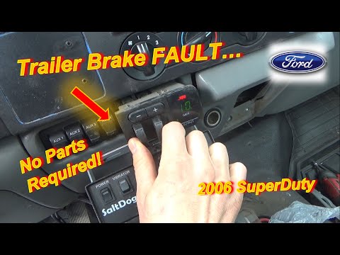
Ford Module Diagnostics and Repair
Learning Outcomes
- Isolate module failures from circuit faults using voltage drop and connectivity testing.
- Identify symptoms of corrupted module communication within the CAN bus network.
- Execute module programming and configuration protocols using OEM-standard tools.
Advanced Ford Module Troubleshooting Protocols
Ford electronic modules process sensor data to command mechanical outputs. Faulty modules frequently mimic mechanical failures or wiring shorts. Eliminate external variables before condemning hardware. Verify stable power and clean grounds at the module connector. Inspect pins for tension loss or corrosion.

A no communication status typically indicates a compromised data link rather than a dead processor. Use an oscilloscope to verify CAN bus signal integrity. If testing confirms hardware failure, replacement requires Programmable Module Installation (PMI). This syncs the module with the vehicle identification number (VIN) and software configurations. Skipping this results in anti-theft lockouts.

Never replace a module based solely on a Diagnostic Trouble Code (DTC). DTCs pinpoint the affected circuit but do not prove internal failure. Validate the wiring harness and related sensors before authorizing replacement.
- Measure source voltage at module connector pins under load.
- Perform a resistance check on the communication network (60 ohms for high-speed CAN).
- Use a bidirectional scan tool to trigger module-controlled actuators manually.
- Inspect the harness for chafing or heat damage near the engine block.
- Verify latest calibration files via Ford Service Information before hardware replacement.
Pro-Tip: Maintain battery voltage above 12.6V during programming to prevent data corruption and permanent hardware bricking.



No Comments Yet
Be the first to comment on this article.