Curtis.Castiglione@ROzebra.com

Brake Assist Systems: Panic Stop Logic and Hydraulic Amplification
Technical Overview
Brake Assist Systems (BAS) function as predictive safety enhancements designed to compensate for insufficient driver-applied pedal force during emergency events. While conventional vacuum boosters provide a constant gain, BAS utilizes electronic monitoring to identify the signature of a panic stop. By transitioning the hydraulic control from a driver-modulated state to a system-governed state, BAS ensures the vehicle reaches the Anti-lock Braking System (ABS) intervention threshold in the shortest possible timeframe. This shift in logic is critical because empirical data indicates that most drivers apply the brakes quickly in an emergency but fail to reach the physical pressure required for maximum deceleration.
Detection Logic for Emergency Maneuvers
The Brake Control Module (BCM) or Electronic Stability Control (ESC) unit identifies emergency stop maneuvers by continuously sampling data from the Brake Pedal Position (BPP) sensor and the master cylinder pressure transducer. The logic is predicated on the velocity of application rather than the total displacement of the pedal.
- Application Velocity (dV/dt): The system calculates the rate of change in pedal travel. If the displacement velocity exceeds a pre-defined threshold, measured in millimeters per millisecond, the ECU categorizes the event as a panic maneuver. This allows for intervention even if the pedal stroke is only partially complete.
- Pressure Gradient: The system monitors the rate of hydraulic pressure rise within the primary circuit. A steep pressure gradient occurring within a narrow temporal window triggers the amplification logic, even if the absolute pressure remains below the lock-up threshold.
- Comparative Analysis: In modern integrated power brakes (IPB), the system compares pedal travel against wheel speed deceleration. If high-velocity pedal input is detected without an immediate, proportional drop in wheel speed, the BAS logic assumes the driver is hesitating or mechanically disadvantaged and initiates full pressure.
Hydraulic Amplification and Driver Override
Upon detection of a panic event, the system overrides the driver's physical input to reach the maximum hydraulic pressure threshold instantly. This process bypasses the standard mechanical-hydraulic ratio to prioritize immediate deceleration.
- Solenoid Command: The ECU energizes the high-pressure switching valves within the hydraulic modulator. This action isolates the master cylinder from the wheel circuits and connects the wheel circuits directly to the high-pressure accumulator or the internal motor-driven pump.
- Pressure Saturation: The system forces the hydraulic fluid to the saturation point where ABS intervention begins. This occurs within 50 to 100 milliseconds, significantly faster than a human operator can mechanically depress the pedal to the floor.
- Deactivation Logic: The system maintains this maximum pressure as long as the driver maintains pressure on the pedal. The override is cancelled only when the BPP sensor detects a significant decrease in pedal stroke velocity or a return toward the rest position, signaling the end of the emergency maneuver.
Failure Analysis and Diagnostics
Failure in the BAS logic often results from sensor drift or communication latency on the Controller Area Network (CAN). Diagnostic protocols must focus on the accuracy of the input signals and the response time of the actuators.

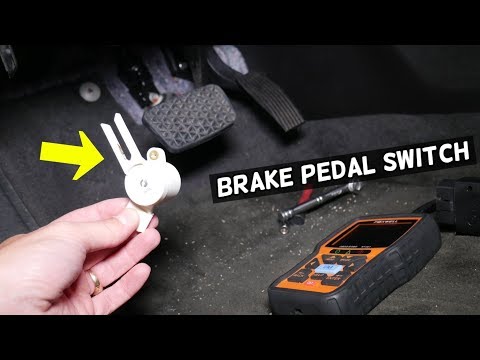
- Serialized Data Sweep: Perform a sweep of the Brake Pedal Position (BPP) sensor and the master cylinder pressure transducer using a diagnostic tool. Verify that the signal output is linear and free of signal dropouts. Any discontinuity in the voltage sweep can cause the ECU to miscalculate the application gradient, leading to unintended BAS deployment or a failure to deploy during a legitimate emergency.
- Bidirectional Solenoid Integrity Test: Manually cycle the BAS-specific intake and bypass valves while monitoring the amperage draw and the hydraulic pressure response. Excessive amperage indicates internal solenoid friction, while a slow pressure rise indicates a failing high-pressure pump or internal seal leakage within the modulator.
- Pedal Feel Simulation and Latency Check: With the vehicle stationary, use the scan tool to monitor the Time to ABS Threshold during a simulated panic application. If the delta between the BPP sensor movement and the achievement of maximum system pressure exceeds 150ms, inspect the hydraulic circuit for air entrainment or check for firmware corruption in the Brake Control Module.
Written by Curtis Castiglione



No Comments Yet
Be the first to comment on this article.